Three Phase Induction Motor Wiring Diagram
Three phase motor connection schematic power and control wiring installation diagrams. There are a number of different construction methods used, but the basic principle is the same.
3 hp (2.2kW) 3 phase 6 pole AC Induction Motor
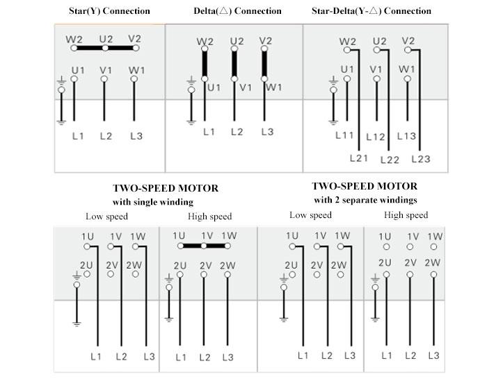
It also shows the difference between delta and star connect.

Three phase induction motor wiring diagram. 11 three phase motor control circuit diagram. How to wire a motor starter | library.automationdirect for 3 phase 240v motor wiring diagram, image size 576 x 511 px, and to view image details please click the image. Motor configured for high voltage.
3 phase forward reverse switch wiring diagram earth bondhon reverse delta connection switch. Despite this direct connection, no harm is done to the motor. The basic diagram (view a) shows a circle with two leads labeled t1 and t2.
The first step is to figure out the voltage of your phases. Diagram dd6 diagram dd8 m 1~ ln e diagram dd9 m 1~ ln e white brown blue l1 l2 n s/c bridge l1 and l2 if speed controller (s/c) is not required diagram dd7 ln e l1 l2 n s/c z2 u2 z1 u1 cap. Three phase induction motor blow up diagram of construction parts induction electrolytic capacitor motor works.
When you make use of your finger or perhaps the actual circuit with your eyes, it is easy to mistrace the circuit. You will be in a position to learn precisely when the projects needs to be completed, which makes it easier to suit your needs to properly control your time. Figure 1 typical wiring diagram.
Two chief sections of the engine are both rotor and stator. 3 phase electric motor brake wiring diagram. Three phase motor connection schematic, power and control wiring installation diagrams.
Suited to a variety of applications, this totally. Three phase induction brake motors show tell ac reversible and electromagnetic motor 90 watt 40 method for braking. In short this the complete guide of forward reverse.
36 slots 3 phase 6 pole induction motor. A dol starter (also known as a direct on line starter or across the line starter) is a method of starting a 3 phase induction motor. It reveals the elements of.
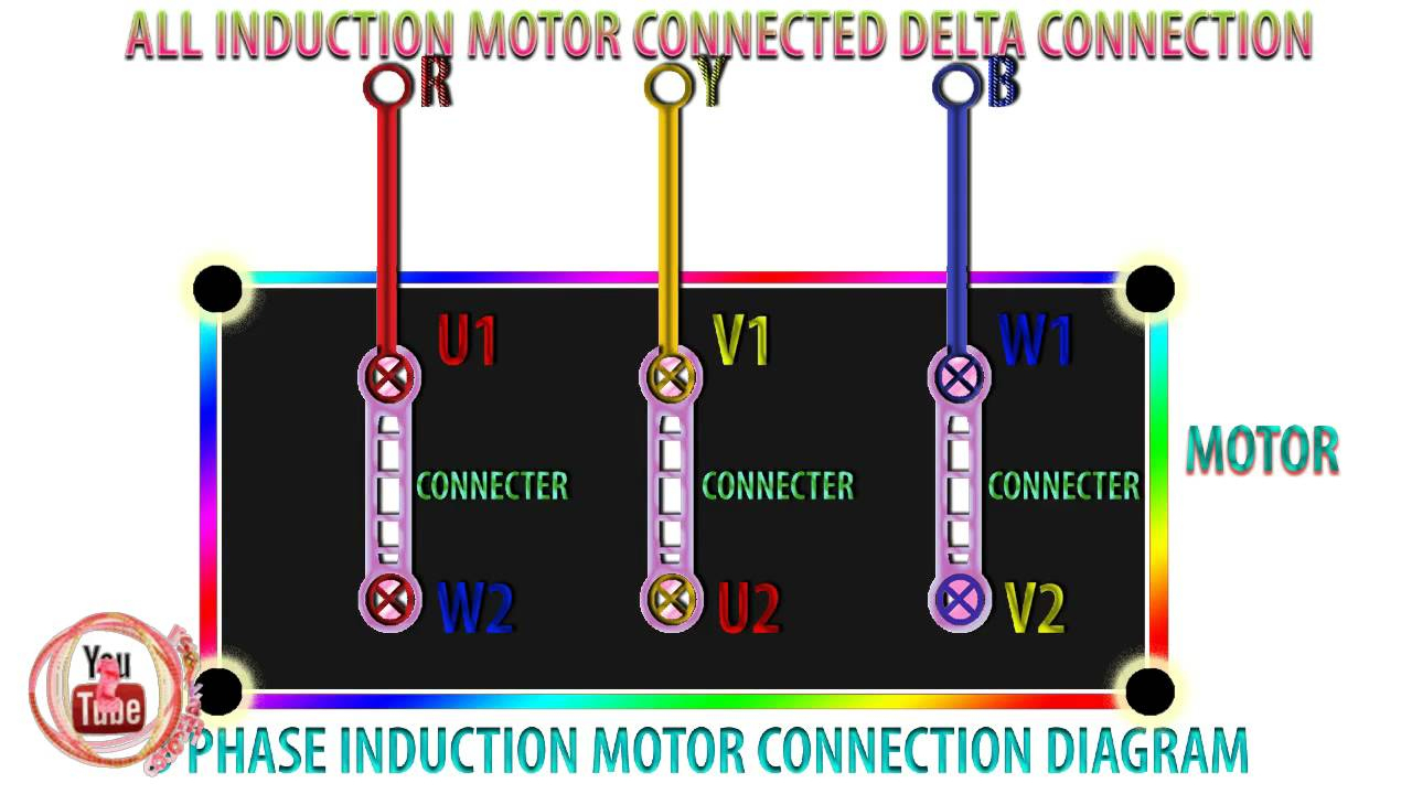
It has quite good efficacy and low manufacture and preserves costs. For three phase motor wiring in star or delta so not really appropriate to single phase application. Squirrel cage induction motor circuit diagram.
I've recently bought a clarke induction motor with these specs: 1 trick that we 2 to printing a similar wiring plan off twice. The stator of the squirrel cage induction motor fig.
• the basic idea of an electric motor is to generate two magnetic fields: Split phase capacitor run induction reversible reactor start. The original wiring diagram showed the proper arrangement of windings to create a larger wye system in which there are four equal windings between any two leads.
That being said, there is a wide range of different motors and what you have on hand can be completely different. For most shore facility applications, this is the case. Three phase motor connection reverse and forward power and control wiring diagrams (two direction one speed) abbreviations:o/l = over load relayno = normally opennc = normally closerev = reverse for =.
3 phase induction motor diagram pdf. Those nine leads provide an option for supplying power from either high or low voltage sources. Rotor magnetic field and stator magnetic field and make the stator field rotating.
A 3 phase squirrel cage induction motor is a type of three phase induction motor which functions based on the principle of electromagnetismit is called a squirrel cage motor because the rotor inside of it known as. Pin on 3 phase wiring. In the united states, for low voltage motors (below 600v), you can expect either 230v or 460v.
3 phase motor starter wiring diagram pdf print the electrical wiring diagram off and use highlighters in order to trace the circuit. Clarke single phase induction motor wiring diagram. For the low voltage option, the instructions show to connect the following:
A wiring diagram is a simplified conventional pictorial depiction of an electric circuit. A three phase motor must be wired based on the diagram on the faceplate. The rotor will constantly be turning to align its magnetic field with that of the stator field.
WIRING DIAGRAM STARDELTA CONNECTION IN 3PHASE INDUCTION MOTOR ELECTRICAL WORLD WIRING

WIRING DIAGRAM STARDELTA CONNECTION IN 3PHASE INDUCTION MOTOR ELECTRICAL WORLD WIRING

🔴 Stardelta connection of a three phase Induction Motor 😍 Save, share and please fol… Delta

Three Phase Motor Wiring Diagram Wiring Diagram
Motor Control for 3 Phase Induction Motors

3 Phase Induction Motor Wiring Diagram

3 Phase Motor With Capacitor Wiring Diagram PURSUEAROUNDME

3 Phase Induction Motor Equivalent Circuit Diagram Wiring Diagram

How to troubleshoot 3 phase Induction motor Step by Step Guide Engineer's Portal
3 Phase Induction Motor Wiring Diagram Collection Wiring Diagram Sample

Why do we need a starter for a threephase induction motor? Quora
3 Phase Induction Motor Wiring Diagram For Your Needs
Why will a 3 phase AC supply produce a rotating field only in an induction motor but
Three phase induction motor working principle

3 Phase Induction Motor Wiring Diagram Collection Wiring Collection
Wiring Diagram Of Direct On Line Starting Three Phase Induction Motor Wiring Diagram and Schematic
3Phase Induction Motor with Help of Industrial Star Delta Starter Circuit diagram, Motor

A typical 3phase induction motor EEE ECE Electrical engineering books, Motor, Electrical

Reversing Three Phase Induction Motors Electrical A2Z