Charging Alternator Wiring Diagram
Wiring diagram arrives with several easy to stick to wiring diagram directions. All products, plans & diagrams, solar wiring diagrams tag:
Mitsubishi 4 Pin Alternator Wiring Diagram Auto Electrical Wiring Diagram

If the relay (must have a nc contact) and the lamp are connected as shown in fig.

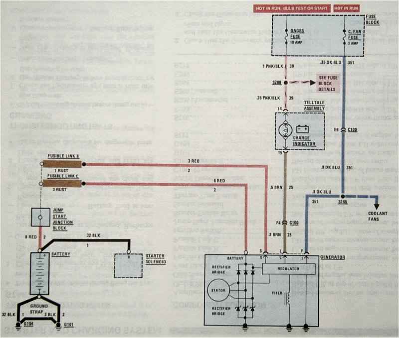
Charging alternator wiring diagram. Diagram #1 shows the basics of the early alternator / voltage regulator (vr) design. The pdf shown here is for a gm cs 130 and cs 144. Does it check the vehicle’s voltage internally or from an outside source?
• ig is the ignition input that turns on the alternator/regulator assembly. Da plug connects to the coil + terminal through the ballast resistor if there is one. Wiring diagram (external electromechanical voltage regulator) refer to the simple diagram below for systems with an external electromechanical voltage regulator.
Wires going into this alternator. If used for 6 volt, make all the wires heavier by 2 gauges. This wiring configuration will excite the alternator to start charging when the engine is running at low rpm’s.
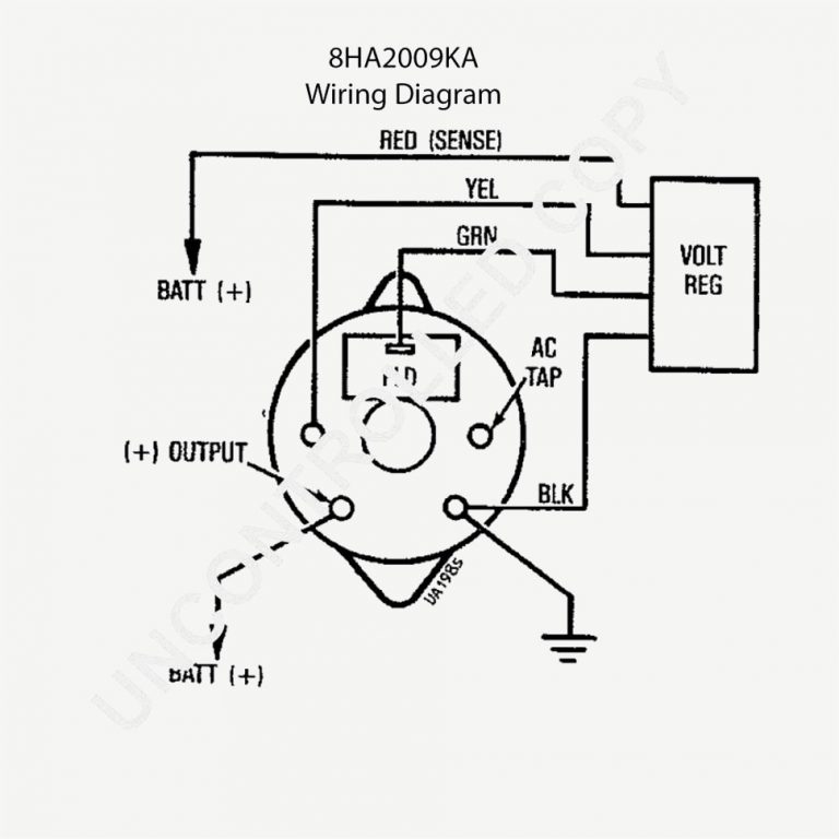
The other brush is the (+) brush (or field) and attached to it is a green wire that routes over to the voltage regulator (which is. Wire if needed and other necessary wiring. Connect alternator to balmar regulator wiring harness as indicated in wiring diagram included on page 12.
Wiring diagram arrives with several easy to stick to wiring diagram directions. 1990 chevy alternator wiring diagram. It will light up when the alternator is not charging, like a conventional charge indicator.
A typical alternator wiring diagram with an external electromechanical voltage regulator. The gnd brush is grounded with the brush mounting screw. One wire alternators eliminate the unsightly factory wiring harness and simplifies installation by using only one wire for charging.
How to wire your hot rod. • s is used by the regulator to monitor charging voltage at the battery. This is the wiring diagram for a typical alternator.
If a new regulator is being installed along with the alternator complete its wiring. The alternator and generator wiring circuit works on a reverse live circuit. (fig 2) balmar alternator wiring with indication lamp
The 6 awg wire in the diagram will take the place of the oem wire you are to remove. First is the heavy gauge wire that is attached to the main post of the alternator that goes right to the battery. These guidelines will likely be easy to grasp and apply.
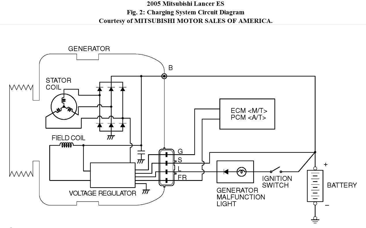
Same voltage as the alternator. If you are having trouble hooking the alternator up i just uploaded a video explaining how to do it, sorry i got a little ahead of myself in this videoif car. • four wires connect the alternator to the rest of the charging system.
All modern charging systems use some form of regulation that’s purely electronic. Charging system the alternator supplies power for the vehicle when the engine is running and engine speed is above idle. Reconnect the ground cable start the engine and using a vom.
Charging system handles all of the vehicle’s electrical requirements. The alternator’s positive and ground cables should be sized according to the chart on page 3. 400+ amp hours of battery storage capacity.
Note the alternative positions for the voltage regulator and also the surge quench diode. This diagram was designed for 12 volt systems, but can also be used for 6 volt systems. One of the key differences is how the internal voltage regulator determines charge rate.
The ignition input wire is attached to the engine. • l is the wire the regulator uses to ground the charge warning lamp. R simply connect one wire from the positive battery terminal to the positive alternator terminal.
Charge wire connects from the alternator to the battery through the the resistor or directly to the key switch itself (switched side). • b is the alternator output wire that supplies current to the battery. The alternator is charging at least 13.8 volts @ 1,000 engine rpm’s.
It’s supposed to assist all the typical user in developing a suitable method. All the ecu programming tools available on the site are engineered intricately oct 27 2020 ecu flash tool is a free tool to upgrade the ecus program memory firmware. When an alternator has its output disconnected whilst the engine is running, the sudden stopping of current flow through the stator causes the.
There are 2 brushes in the alternator, each one has a field terminal, one is labeled fld, the other is labeled gnd. Gm alternator wiring gm alternator wiring. For example 14 gauge wire will become 12 gauge, 10 gauge will be 8 gauge, etc.
1990 chevy engine wiring diagram. 2 the lamp will go out when the alternator is charging the batteries. Gm has many different alternators and each has its own alternator wiring diagram and alternator symptoms.
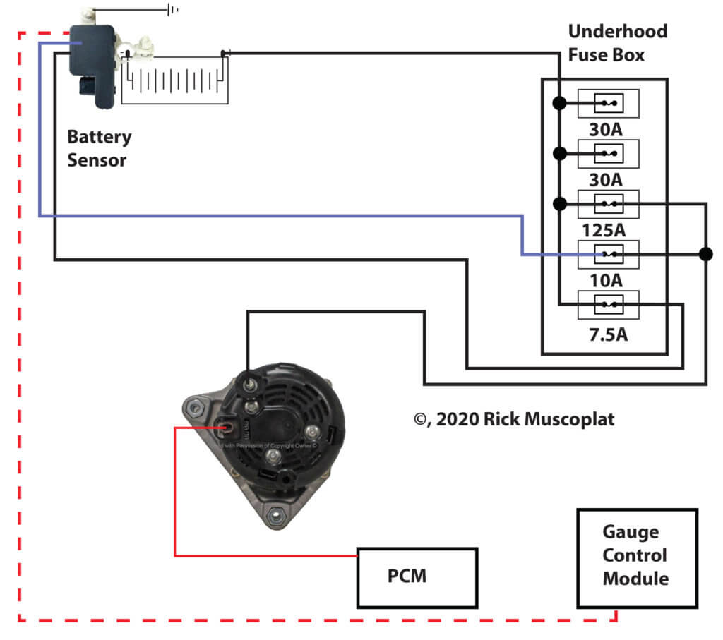
1990 honda alternator wiring diagram moreover fuel pump wiring diagram picture delux 14 in addition coach batteries not charging.a wiring diagram is a simplified traditional photographic representation of an electric circuit. The circuit comprises three main wires: Battery positive cable, voltage sensing wire, and ignition wire.
Pictures John Deere Alternator Wiring Diagram Charging Long Tractor Ford Alternator Wiring
Charging System Upgrade with a Tuff Stuff Alternator Hot Rod Network

Simple alternator wiring diagram Alternator, Car alternator, Automotive repair

Charging System Wiring For A Bodies Only Mopar Forum
alternator wiring Third Generation FBody Message Boards
Delco 12si Alternator Wiring Diagram Download

Troubleshooting An Alternator Warning Light BMW Car Club of America

Cat Diesel Generator Wiring Diagram Alternator Charging wiring diagram DB

9498 Mustang Alternator Starting and Charging Wiring Diagram
Honda alternator and charging systems explained — Ricks Free Auto Repair Advice Ricks Free Auto
Wiring Diagram Alternator Warning Light

CHARGING SYSTEM ALTERNATOR in 2021 Alternator, Diagram, Free energy generator

Charging System 12 Volt Alternator Wiring Diagram Collection

New Wiring Diagram Car Charging System diagram diagramtemplate diagramsample Alternator

Alternator Charging System Wiring Diagram HAISAYACARLMILIA

Alternator Wiring Hi, I Need Help in Determining What Is the Use
Alternators & Charging System Illustrations
Alternator Charge Wire Boat Wiring Diagram Wiring Forums

Amc Charging System And Alternator Wiring Forums
